

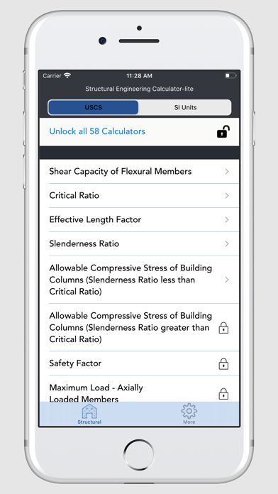

Structural Engineering Calculator contains 58 calculations of different structural and civil engineering parameters.
Available in Imperial (USCS) and Metric Units (SI Units).
List of 58 Calculators:
1.Shear Capacity of Flexural Members
2.Critical Ratio
3.Effective Length Factor
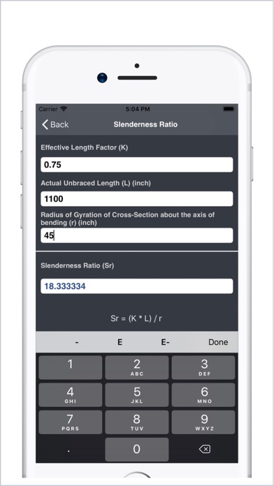
4.Slenderness Ratio
5.Allowable Compressive Stress of Columns (Slenderness Ratio less than Critical Ratio)
More Calculators Available for In-App Purchase:
6. Allowable Compressive Stress of Columns (Slenderness Ratio greater than Critical Ratio)
7. Safety Factor
8. Maximum Load - Axially Loaded Members
9. Allowable Bending Stress (Compact Members)
10. Allowable Bending Stress (Non-Compact Members)
11. Moment Gradient Factor
12. Allowable Stress - Compression Flange
13. Plastic Moment
14. Maximum Unbraced Length for Plastic Design (I-Shaped Beams)
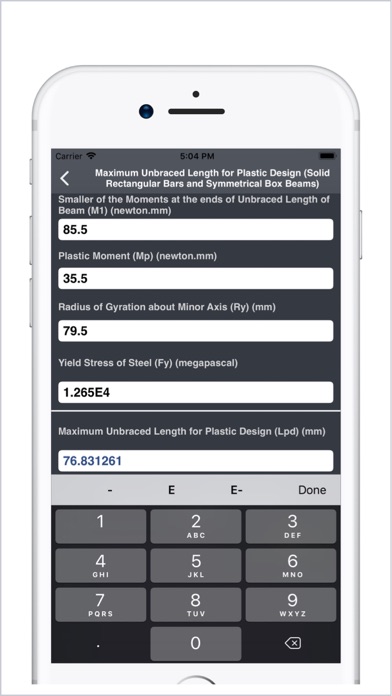
15. Maximum Unbraced Length for Plastic Design (Solid Rectangular Bars and Symmetrical Box Beams)
16. Laterally Unbraced Length - Full Plastic Bending Capacity (I Shapes and Channels)
17. Laterally Unbraced Length - Full Plastic Bending Capacity (Solid Rectangular Bars and Box Beams)
18. Laterally Unbraced Length - Full Plastic Bending Capacity (Solid Rectangular Bars Bent About Major Axis)
19. Limiting Buckling Moment
20. Nominal Moment (Compact Beams)
21. Critical Elastic Moment - Compact Beams
22. Critical Elastic Moment - Solid Rectangular Bars and Symmetrical Box
23. Allowable Shear Stress
24. Allowable Shear Stress with Tension Field Action
25. Area Required by the Bearing Plate (Plate Covering the Full Area of Concrete Support)
26. Area Required by the Bearing Plate (Plate Covering Less Than the Full Area of Concrete Support)
27. Minimum Plate Thickness
28. Area Required for a Base Plate Under a Column Supported by Concrete
29. Plate Length
30. Thickness of Plate (Cantilever Bending)
31. Flange Thickness (H-Shaped Column)
32. Web Thickness (H-Shaped Columns)
33. Actual Bearing Pressure Under the Plate
34. Allowable Bearing Stress (Rollers/Rockers)
35. Web Depth/Thickness Ratio (Unstiffened Web)
36. Web Depth/Thickness Ratio (Transverse Stiffeners)
37. Deflection at the Top (Wall with Solid Rectangular Cross Section)
38. Deflection at the Top (Shear Wall with a Concentrated Load at the Top)
39. Deflection at the Top (Fixed Wall Against Rotation at the Top)
40. Combined Axial Compression (Ratio of Computed Axial Stress to Allowable Axial Stress less than 0.15)
41. Combined Axial Compression (Ratio of Computed Axial Stress to Allowable Axial Stress less than / equal 0.15)
42. Axial Stress for a Concentrated Load (Applied at a Distance Larger Than the Depth of the Beam from the End of the Beam)
43. Axial Stress for a Concentrated Load (Applied Close to the Beam End)
44. Concentrated Load of Reaction (Applied at a Distance from the Beam End of at Least Half the Depth of the Beam)
45. Concentrated Load of Reaction (Applied Closer Than Half the Depth of the Beam)
46. Relative Slenderness of Web and Flange
47. Total Column Load (Relative Slenderness of Web and Flange less than 2.3)
48. Total Column Load (Relative Slenderness of Web and Flange greater than 1.7)
49. Combined Cross-Sectional Area of a Pair of Column-Web Stiffeners
50. Column Web Depth Clear of Fillets
51. Thickness of Column Flange
52. Allowable Bearing Stress on Projected Area of Fasteners
53. Maximum Unit Stress in Steel
54. Maximum Stress in the Bottom Flange
55. Number of Shear Connectors
56. Total Horizontal Shear (Based on Area of Concrete Flange)
57. Total Horizontal Shear (Based on Area of Steel Beam)
58. Total Horizontal Shear (Based on Area of Longitudinal Reinforcement)